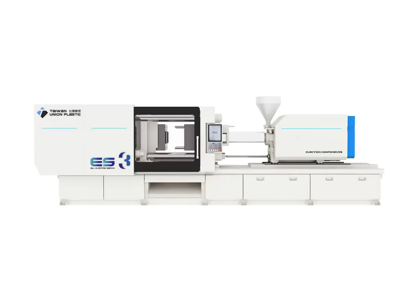
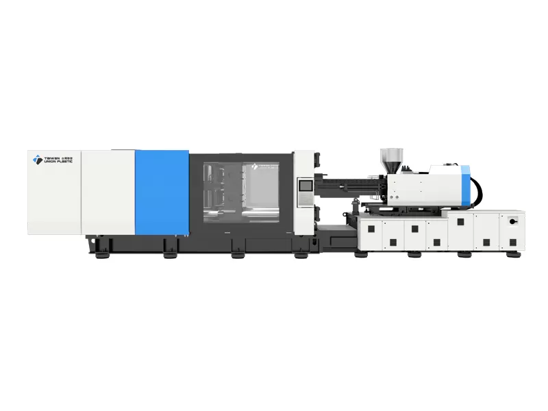
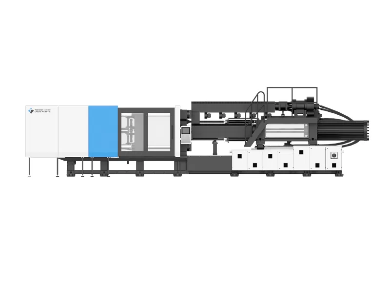
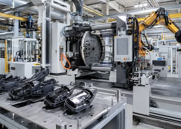
All-electric injection molding machines feature high precision, high efficiency, energy conservation and environmental protection, high level of intelligence, and wide range of application scenarios.

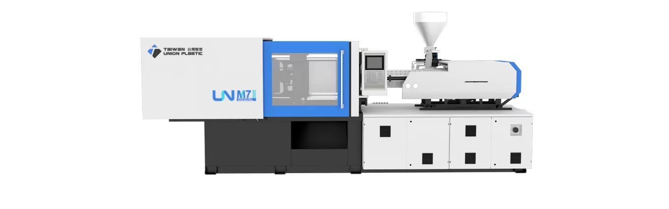 UN
Servo Hydraulic Injection Molding Machine
UN
Servo Hydraulic Injection Molding Machine
Choosing the right injection molding machine begins with understanding how different machine architectures create, control and repeat the forces needed to melt resin, fill a mold, hold pressure, cool the part and eject it. Buyers often start with a simple question such as “electric or hydraulic?”, but a practical B2B decision usually involves more variables: mold dimensions, projected area, shot size, required injection speed, material behavior, part tolerance, cycle-time target, automation level, plant utilities and the expected production life of the program.
For that reason, the most useful way to compare machines is not to rank one technology as universally better. Instead, manufacturers should match the machine architecture to the production problem. TUP develops injection molding equipment across a broad range of mainstream configurations, with published clamping-force coverage from approximately 90 to 6600 metric tons. This range allows a buyer to compare compact precision systems, conventional servo-hydraulic machines, two-platen platforms for large molds, electric and hybrid systems, multi-component equipment and application-specific machines within one technology framework.
Injection molding machine types are commonly classified by drive system, clamping structure, injection-unit configuration and the special process the machine is designed to perform.
At the highest level, the market is usually divided into hydraulic, all-electric and hybrid injection molding machines. That classification describes how the main machine movements are powered. Hydraulic machines use hydraulic pressure for major movements; all-electric machines use servo motors for the primary molding axes; hybrid machines combine hydraulic and electric functions so that each drive technology is used where it offers the best process advantage.
However, drive type alone does not tell a buyer enough. A two-platen machine and a three-platen toggle machine can both be servo hydraulic, yet their mold-space efficiency and suitability for very large tools can be very different. A multi-component machine can be hydraulic, electric or hybrid, while its real differentiator may be the number and orientation of injection units, the rotary table arrangement or the way the mold transfers a part between cavities.
For procurement teams, the safest starting point is therefore to create a machine map. First define the drive platform. Second define the clamping structure. Third define the required injection capacity and speed. Fourth define any special process such as two-color molding, IML, insert molding, compression injection molding, PET preform molding, PVC fitting molding or thin-wall packaging. TUP’s injection molding machine types page provides a useful overview of these families and their clamping-force ranges.
That hierarchy also prevents a common SEO and purchasing mistake: treating “injection molding machine” as one interchangeable product. In reality, different architectures are optimized around different constraints. The machine that is ideal for a clean, high-precision medical component may be economically inefficient for a large pallet. A two-platen press that comfortably carries a very large automotive mold may be unnecessary for a small optical component. The correct choice is the one that creates the required process window with adequate reserve, without paying for capability the application does not need.
Electric injection molding machine types use servo motors to control major molding movements, enabling precise position, speed and force control without relying on a central hydraulic power system for those axes.
All-electric machines are frequently selected when repeatability, clean production, rapid response and energy management have high value. Each major movement can be controlled by an electric servo system, allowing the machine to execute injection, plasticizing, mold movement and related motions with tightly managed profiles. Because servo drives can respond quickly to command changes and do not need a continuously operating hydraulic pump, the machine architecture can also reduce idle energy losses in suitable applications.
TUP publishes several useful reference figures for its ES all-electric platform. The ES series covers approximately 90–450 metric tons of clamping force. TUP also states an injection-position accuracy of 0.01 mm, a maximum injection speed of 450 mm/s and a screw speed of 400 rpm for the platform. On its product page, TUP reports 20% faster mold opening and closing, injection response below 40 ms and energy consumption 20%–40% lower than traditional injection molding machines under the stated comparison conditions. These figures should be interpreted as platform specifications or manufacturer-reported performance rather than universal results for every mold and resin.
An all-electric machine is particularly attractive when the molded part has a narrow processing window. Medical consumables, optical and electronic parts, high-cavity precision products, small technical components and certain packaging applications can benefit from accurate position control and repeatable injection profiles. The cleaner drive architecture can also be useful where the molding cell is designed around stricter contamination controls.
Yet electric equipment should not be selected only because the word “precision” appears in the project specification. Mold size, ejection force, core-pull requirements, peak injection pressure and the economics of maintenance still matter. Buyers comparing an all electric injection molding machine should review the complete mold data sheet and expected production recipe, not simply the nominal tonnage.
Hydraulic injection molding machine types use hydraulic pressure to create and control machine movements, providing robust force capability and broad adaptability across materials, molds and part sizes.
Hydraulic machines remain important because they offer a mature, flexible way to generate high force. Modern servo-hydraulic designs differ significantly from older fixed-pump systems. A servo motor can regulate the hydraulic pump according to process demand, reducing unnecessary energy use and improving response compared with a continuously running conventional hydraulic circuit.
For many general-purpose industrial applications, servo hydraulics provide an effective balance of purchase cost, mold compatibility, clamping force and process flexibility. Large household components, automotive parts, industrial containers, construction products and many consumer goods do not automatically require an all-electric architecture. What they require is a stable machine that can repeatedly hold the mold, fill the cavity, maintain pressure and manage the required auxiliary motions.
TUP’s UN platform is positioned as a servo-hydraulic series focused on stable, efficient production. A buyer evaluating a servo hydraulic injection molding machine should compare hydraulic response, platen rigidity, mold protection, repeatability, oil-temperature management and servo-pump sizing, rather than using only the label “hydraulic.”
Hydraulic systems are also useful when the mold requires multiple hydraulic functions such as core pulls, unscrewing mechanisms or other auxiliary movements. Even when an electric machine can support those requirements, the total integration cost may lead to a different purchasing decision. The correct comparison is therefore based on the complete molding cell, not on the press alone.
Hybrid injection molding machine types combine electric and hydraulic drive technologies so that high-speed, high-precision actions can be paired with hydraulic clamping or other force-intensive functions.
A hybrid machine is not simply a compromise between electric and hydraulic designs. In the right application, it can be a deliberate optimization. For example, an electric injection unit can provide fast and repeatable screw movement while a hydraulic clamping unit supplies the mold-closing force. This can be attractive for packaging, automotive, consumer products and other applications where injection dynamics and mold size both matter.
TUP’s UN-E platform combines a hydraulic clamping system with an electric injection unit. The company states that the system supports molding speeds up to 450 mm/s. TUP also offers the HS-E two-platen hybrid platform, which pairs a two-platen clamping structure with electric injection and covers approximately 450–3300 metric tons of clamping force. Those configurations illustrate why “hybrid” should be treated as a family of architectures rather than one fixed machine design.
Hybrid equipment can be a strong option when a buyer wants to improve injection response and process repeatability without giving up hydraulic functions or a large mold envelope. It may also make sense when an existing factory already has hydraulic maintenance capability but wants higher performance on the injection side. The total energy result, however, depends on the actual cycle, part weight, cooling time, motor loading and auxiliary equipment. EUROMAP 60.1 specifically notes that energy-efficiency comparisons should be made between machines of similar size and under comparable test conditions, which is an important caution when evaluating supplier claims.
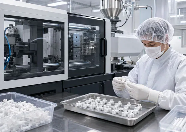
Injection molding machine types for large parts are selected primarily around required clamping force, mold dimensions, opening stroke, daylight, platen size, shot capacity and the physical efficiency of the clamping structure.
As part size increases, nominal tonnage becomes only one part of the decision. A mold can require a large platen and wide tie-bar spacing even when the projected-area calculation does not demand the highest available clamping force. Large automotive parts, appliance housings, pallets, logistics bins and industrial components can also need substantial opening stroke and mold thickness capacity.
This is where two-platen technology becomes important. TUP’s HS two-platen hydraulic series covers approximately 450–6600 metric tons and uses a two-platen structure with a large mold space. By eliminating the traditional third platen and associated toggle package, a two-platen machine can use its length more efficiently, which can be valuable in large-tonnage installations.
Large-part selection should therefore begin with the mold drawing. Verify mold width and height, mold thickness, tie-bar spacing, locating-ring details, ejector layout, core-pull circuits, mold weight and lifting method. Then check the part’s projected area, material and cavity-pressure requirement. Only after these conditions are confirmed should the team finalize clamping force.
Oversizing can be expensive. A machine with far more clamping force and injection capacity than required can increase capital cost, floor-space demand and operating expense. Undersizing is equally risky because the mold may not physically fit, or the press may operate too close to its maximum clamp or injection limits. For that reason, mold-fit verification and process simulation should be treated as a pair.
Multi-component injection molding machine types use two or more injection units and a controlled transfer method to mold multiple colors or materials into one integrated product.
Multi-component molding changes the machine-selection logic because the press must coordinate more than one melt stream. A two-color toothbrush handle, automotive lighting component, soft-touch housing or decorated consumer part can require two injection units, a rotary table, a rotating core, an index plate or another transfer mechanism. The ideal machine depends on part geometry, sequence, material compatibility and mold design.
TUP offers several multi-component configurations, including HD, HS-W, HS-D and hybrid multi-component platforms. The HS-D series, for example, combines a two-platen structure with modular injection-unit combinations and is designed for processes from two-color to five-color. The HS-W platform uses opposite injection units and a horizontal rotary-table concept for complex multi-color products. These differences matter because the mold transfer method directly affects cycle sequence, machine footprint and the type of part that can be molded.
When comparing these systems, procurement teams should ask the moldmaker and machine supplier to agree on an interface document. It should identify the number of injection units, shot size for each material, nozzle location, rotary-table load, transfer angle, core-pull sequence and confirmation signals. A multi-component machine is successful only when the machine, mold, robot and control logic are engineered as one system.
Specialized injection molding machine types modify the standard press architecture around the processing behavior, productivity target or automation requirements of a defined product family.
Special machines are valuable when a recurring application has requirements that a general-purpose machine can meet only with extensive options. TUP’s product portfolio includes dedicated solutions for thin-wall high-speed molding, PET preforms, PVC fittings, large plastic barrels, pallets and thermoset or Bakelite applications. Each of these product groups places a different emphasis on the machine.
PVC fitting molding, for example, requires careful control of material residence and processing conditions because rigid PVC is heat sensitive. PET preform production emphasizes plasticizing efficiency, temperature control, multi-cavity stability and integration with downstream bottle production. Thin-wall packaging emphasizes rapid injection, high response, mold movement and automation. Pallets and large industrial parts emphasize shot capacity, clamping structure, recycled-material handling and mold-changing efficiency.
The advantage of a specialized platform is not a marketing label; it is the reduction of engineering uncertainty. A buyer can start from a configuration already oriented toward the process rather than adding one retrofit after another. The trade-off is that the machine specification should be reviewed carefully if the factory expects the press to run unrelated products later. A highly optimized packaging machine may not be the most flexible choice for a future thick-wall technical part.
An injection molding machine types comparison table helps buyers connect each architecture with the process conditions where it creates the strongest technical and economic fit.
| Machine Type | Primary Strength | Typical Selection Driver | Potential Limitation to Review | TUP Example |
|---|---|---|---|---|
| All-electric | Fast response and precise motion control | Precision parts, clean production, repeatability, energy management | Initial investment and auxiliary hydraulic requirements | ES, approx. 90–450 t |
| Servo hydraulic | Broad process flexibility and robust force capability | General industrial production, diverse molds and materials | Hydraulic maintenance, oil temperature and cycle-specific energy use | UN |
| Hybrid | Combines electric injection with hydraulic or mixed functions | High-speed/precision injection with hydraulic clamping flexibility | System complexity and application-dependent payback | UN-E; HS-E |
| Two-platen | Efficient mold space for medium and large molds | Large automotive, appliance, logistics and industrial parts | Machine selection still depends on mold footprint and shot capacity | HS, approx. 450–6600 t |
| Multi-component | Multiple colors/materials in one molding sequence | 2K, multi-color, soft-touch and integrated functional parts | Mold-transfer design and sequence coordination | HD, HS-W, HS-D |
| Thin-wall high-speed | High injection speed and short-cycle capability | Packaging, multi-cavity and lightweight products | Requires high-performance mold, cooling and automation | UN-H, approx. 160–2500 t |
| Application-specific | Machine configured around a material or product family | PET, PVC fittings, pallets, barrels, thermosets | Future product flexibility should be evaluated | PET, PVC, PLT, UN-B, UN-U |
The table should be used as a screening tool rather than a final machine specification. Two projects that both appear to need a 500-ton press can require very different injection units, mold spaces and control options. One may be a thin-wall packaging cell with a fast robot; the other may be a thick industrial housing with long cooling time. Their nominal clamp force can be similar while their ideal machine configurations are not.
Selecting between injection molding machine types means matching the machine’s clamp, injection, drive and automation capabilities to a documented production window instead of selecting by tonnage or price alone.
A disciplined selection process starts with the part and mold rather than the catalog. Buyers should prepare a data package containing the resin grade, part weight, projected area, wall thickness, number of cavities, runner system, required appearance, critical dimensions, mold dimensions, mold weight and expected annual volume. If the project is a transfer from an existing press, include the current cycle time, injection time, peak pressure, cushion, screw recovery time and defect history.
Next, define the production objective. Is the goal to minimize energy per kilogram, maximize parts per hour, reduce labor, improve precision, fit a larger mold into a shorter machine, run multiple colors or establish a clean molding cell? The answer helps determine whether the project should prioritize electric response, hydraulic flexibility, a two-platen structure, a multi-component system or a specialized platform.
The third step is to verify operating margin. A machine should not be selected to run permanently at the edge of its capacity. Autodesk Moldflow guidance notes that a good clamp-force result is below approximately 80% of the machine limit, leaving around 20% as margin, although the actual margin can need to be higher when mold-specific loads are present. Similar reserve should be considered for shot size, injection pressure and plasticizing capacity.
Finally, compare lifetime economics. Purchase price is visible, but energy, maintenance, cycle time, scrap, floor space, mold-change time, auxiliary equipment and downtime can become more important across several years of production. A technically correct machine type creates a wider, more repeatable process window; that stability usually matters more than saving a small percentage on initial equipment cost.
These frequently asked questions summarize the practical differences between injection molding machine types for B2B equipment selection.
The three basic drive categories are hydraulic, all-electric and hybrid. A complete classification should also consider clamping structure, injection-unit arrangement and special process requirements.
All-electric machines are often selected for high repeatability because servo motors can directly control major motion axes. Final part precision still depends on the mold, resin, process window, temperature control and measurement system.
No. Modern servo-hydraulic machines remain widely applicable because they provide strong force capability, mold flexibility and mature serviceability. Their suitability depends on the production requirement rather than the age of the technology concept.
A two-platen machine is particularly useful when the mold is large and mold-space efficiency, opening stroke and high clamping force are important. It is common in automotive, logistics, appliance and other large-part applications.
An all-electric machine uses servo-electric drives for the primary molding movements, while a hybrid machine intentionally combines electric and hydraulic systems. A common hybrid arrangement uses electric injection with hydraulic clamping.
No single machine architecture is ideal for every product. Mold dimensions, material, shot size, pressure, speed, cycle time, special processes and automation requirements should determine the machine configuration.
The best injection molding machine type is the one that provides the required process capability, mold compatibility and operating margin at the lowest sustainable total production cost.
Electric, hydraulic, hybrid, two-platen, multi-component and specialized machines each solve a different set of manufacturing constraints. Buyers get better results when they move beyond a simple technology label and evaluate the complete molding system: part, resin, mold, machine, automation, utilities and quality target.
TUP’s broad platform coverage gives manufacturers the ability to evaluate different machine architectures against the same application data. For a new project, the most useful RFQ package is not simply “we need a 500-ton machine.” It is a complete description of the molded product, mold dimensions, material, production target and process requirements. That information allows the machine supplier to recommend an architecture with enough capability and reserve while avoiding unnecessary oversizing.