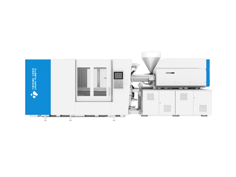
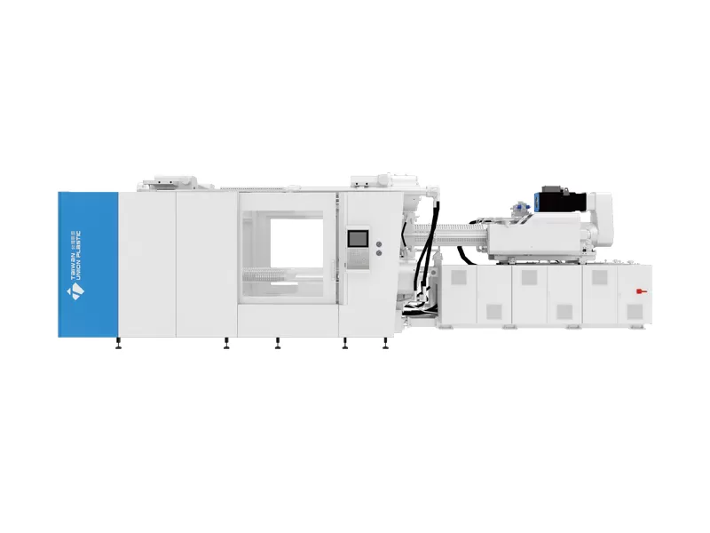
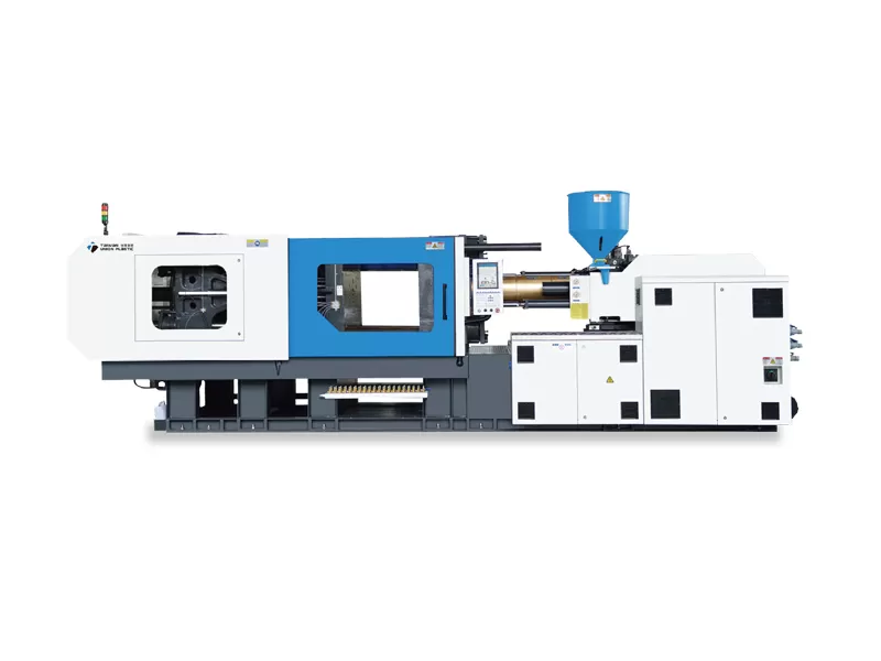
It combines the advantages of a two-platen clamping structure and an electric injection unit, making it suitable for the precision molding of medium and large-sized products.

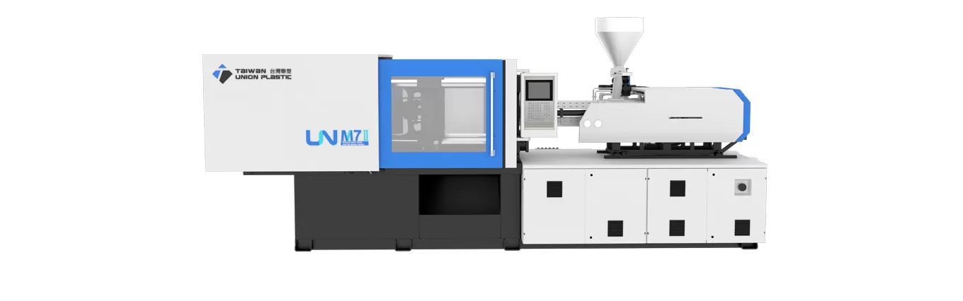 UN
Servo Hydraulic Injection Molding Machine
UN
Servo Hydraulic Injection Molding Machine
Injection molding machine tonnage is one of the first numbers buyers discuss, but it is also one of the most frequently misunderstood. The rated tonnage of a machine describes its maximum clamping-force capacity, not the weight of the machine, the weight of the molded part or the amount of plastic it can inject. A correct machine selection therefore cannot start with a rule such as “this part weighs 500 grams, so it needs a 500-ton press.”
The engineering question is different: how much force will the pressure inside the mold generate in the direction that tries to separate the mold halves, and how much machine capacity is needed to resist that force with a suitable operating margin? Projected area and cavity pressure are the two central variables. Mold dimensions, injection pressure, material viscosity, gate design, number of cavities, runner area, core pulls and part geometry then determine how much margin is sensible.
This guide explains the calculation in a way that purchasing teams, mold engineers and production managers can use together. It also shows why the calculated tonnage is only one checkpoint. The mold still has to fit the tie-bar spacing and platen, the shot size must be appropriate, the injection unit must deliver the required pressure and speed, and the molding cell must meet the production target.
Injection molding machine tonnage is the rated clamping-force capacity that the machine can apply to keep the mold closed during filling and packing.
Clamping force is a force, so the SI unit is the newton. Injection molding equipment is nevertheless commonly marketed in metric tons of force or US tons of force, which can create confusion because “ton” is also used as a unit of mass in everyday language. NIST lists the exact conversion of one kilogram-force as 9.80665 newtons. Therefore, one metric tonne-force equals 9.80665 kilonewtons.
That distinction matters when a project team is exchanging data internationally. A mold simulation may report clamp force in kilonewtons, a machine catalog may use metric tons, and another supplier may quote US short tons. Before comparing machines, confirm the unit system. A 500 metric-ton machine is not exactly the same as a 500 US-ton machine.
TUP’s equipment portfolio illustrates how widely the requirement can vary. The company states that its overall injection molding machine range spans approximately 90–6600 metric tons. Its ES all-electric platform covers approximately 90–450 tons, while the HS two-platen hydraulic series covers approximately 450–6600 tons. Those numbers are useful because they show that tonnage is closely connected to application scale and clamping architecture rather than being an isolated specification.
Injection molding machine tonnage is strongly influenced by projected area because cavity pressure acts across the area of the molded part and runner that is projected onto the mold parting plane.
Imagine the mold viewed directly along the clamp direction. The silhouette of every cavity, and normally the runner system where applicable, contributes to the projected area that is exposed to internal pressure. When molten polymer fills and packs the cavity, that pressure creates a separating force on the mold halves. The clamp must oppose it.
Autodesk Moldflow describes clamp force as a function of injection pressure and projected area. In a detailed simulation, the calculation integrates pressure over many small areas rather than applying one uniform pressure value to the entire part. That is more accurate because cavity pressure is not perfectly uniform throughout filling and packing.
For preliminary equipment sizing, a simplified projected-area method is still useful. The team can estimate the total projected area of all cavities and runners, multiply it by an appropriate estimated cavity pressure, and then add operating margin. The result should be treated as a screening calculation, not a substitute for mold simulation or machine-trial data when the project is sensitive.
This is also why part weight alone is a poor tonnage predictor. A large, shallow panel can have relatively low mass but a very large projected area. A compact, thick technical part can be heavier while requiring less projected area. The two parts can therefore need very different clamping forces even if their shot weights are similar.
Injection molding machine tonnage can be estimated by multiplying projected area by the pressure acting to open the mold, then applying a reserve so the machine does not operate continuously at its maximum clamp limit.
The simplest conceptual relationship is:
Required clamp force = projected area × effective cavity pressure.
When area and pressure use compatible SI units, the result is a force in newtons or kilonewtons. For example, if the projected area is measured in square millimeters and the pressure is measured in newtons per square millimeter, multiplying them gives newtons. Since 1 MPa equals 1 N/mm², this unit system is convenient for engineering calculations.
The difficult part is not the multiplication. It is choosing a defensible pressure value. Machine injection pressure is not the same as average cavity pressure. Pressure drops occur through the nozzle, sprue, runner, gate and flow path, and the pressure distribution changes during filling and packing. Using the machine’s maximum injection-pressure rating across the entire projected area can therefore grossly overstate the clamp requirement.
For an existing mold, use measured or simulated cavity-pressure information where possible. For a new mold, Moldflow or another validated process simulation can estimate the pressure distribution and predicted clamp force. For an early RFQ where detailed analysis is not yet available, the moldmaker and machine supplier should agree on a conservative estimated cavity pressure based on material, wall thickness, flow length, gate design and experience with similar parts.
Autodesk also gives a useful machine-utilization guideline: a good clamp-force result should be below approximately 80% of the machine limit, leaving the remaining 20% as safety margin. The company notes that molds with sliding cores, guide pins and other tool-dependent loads may require a larger margin. This means that a predicted 400-ton clamp demand should not automatically be assigned to a 400-ton machine.
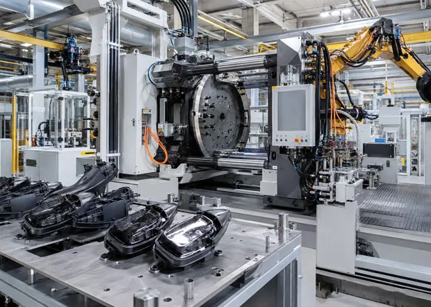
A worked injection molding machine tonnage example converts the part’s projected area and estimated cavity pressure into a clamp-force requirement, then applies an operating margin before machine selection.
Consider a hypothetical four-cavity industrial component mold. Assume that the combined projected area of the four cavities and runner system is 1,200 cm². Assume further that process simulation predicts an effective average pressure contribution equivalent to 300 bar over that projected area at the point of maximum clamp demand. These figures are examples for calculation only, not universal design values.
First convert the pressure into a unit that works with the projected area. One bar equals 0.1 MPa, and one MPa equals 1 N/mm². Therefore, 300 bar equals 30 MPa or 30 N/mm². The projected area of 1,200 cm² equals 120,000 mm².
Multiplying 120,000 mm² by 30 N/mm² gives 3,600,000 N, or 3,600 kN. Using the NIST conversion of 9.80665 kN per metric tonne-force, the predicted separating force is approximately 367 metric tons of clamp demand.
This result is intentionally based on an assumed uniform effective pressure for a simple screening example. A detailed Moldflow analysis would integrate the changing pressure distribution across the cavity rather than applying one value everywhere, so the simulation result should take priority when it is available.
If the target is to keep predicted clamp demand at or below approximately 80% of machine capacity, divide 367 tons by 0.80. The result is about 459 metric tons. In practice, the engineering team would then select the next suitable machine capacity above that value, provided the mold dimensions, opening stroke, shot size and injection unit are also compatible.
This example demonstrates why calculation records should always show units. A spreadsheet containing only “1200 × 300 = 360000” is not enough for an equipment decision. Record whether area is mm² or cm², whether pressure is bar or MPa, whether tonnage means metric tonnes-force or US tons, and whether the pressure figure comes from simulation, cavity measurement or an empirical assumption.
Injection molding machine tonnage increases when the mold presents more projected area or higher cavity pressure, and mold design can change both variables even when the molded product itself is unchanged.
Cavitation is the most obvious example. If one cavity has a projected area of 150 cm², a four-cavity mold does not require the same clamp force as a single-cavity mold. The total projected area of the cavities rises approximately with the number of cavities, and the runner may add additional area. The production benefit of more cavities must therefore be balanced against higher clamping, shot-size and plasticizing requirements.
Gate design also matters. A restrictive gate or long flow path can increase the pressure needed to fill the part, especially with a thin wall or high-viscosity material. If a design change reduces pressure loss, the required clamp force can fall even though the projected area is unchanged. That is one reason machine selection and mold design should not be isolated activities.
Undercuts and slide mechanisms deserve special attention. Autodesk notes that tool-dependent preloads such as sliding cores and guide pins can affect the required safety margin. Simulation geometry can also overpredict clamp force if projected surfaces overlap in certain undercut or stacked-mold situations. Engineers should review how the simulation defines the clamp direction and projected surfaces before using the output as a purchase specification.
Mold dimensions can ultimately override a simple tonnage calculation. A mold may need only 350 tons of calculated clamp force but be too wide to fit a compact 350-ton machine. In that case, the project may need a larger press or a machine architecture with a more generous mold envelope. A two platen injection molding machine can be attractive when large mold capacity and opening space are more important than minimizing nominal tonnage.
Injection molding machine tonnage is affected by resin and part geometry because viscosity, wall thickness, flow length, gate restriction and surface features influence the pressure required to fill and pack the cavity.
Two molds with the same projected area can require different clamp forces. A thick, easy-flowing polypropylene part with a short flow path may fill at a lower cavity pressure than a thin technical component made from a more viscous engineering resin. The second mold can therefore create a larger separating force even if the projected silhouette is similar.
Thin-wall designs are especially sensitive because the polymer cools rapidly against the mold surface. To fill the cavity before the flow front freezes, the process may require higher injection speed and a well-designed runner and gate system. High-speed filling can also create pressure peaks. This is why a thin-wall project should not be sized from a generic tons-per-square-inch rule without checking the actual flow behavior.
Fiber-filled materials can introduce additional considerations. They may require higher injection pressure, more wear-resistant plasticizing components and careful control of orientation and warpage. High-gloss surfaces, textured surfaces and dimensional tolerances can also narrow the acceptable process window. A machine with adequate nominal tonnage but insufficient pressure, injection speed or control resolution can still be the wrong choice.
For early equipment selection, empirical rules can be used as a reasonableness check, but the final decision should rely on the specific resin grade and mold. Material suppliers publish viscosity and processing guidance, while simulation can show pressure loss and clamp demand. Combining those sources creates a much stronger specification than relying on a single industry rule.
A large injection molding machine should be selected only after the clamp-force calculation is cross-checked against mold fit, shot size, injection capacity, opening stroke, ejection, automation and factory-installation limits.
Tonnage can tell you whether the machine can hold the mold closed. It does not tell you whether the mold can physically enter the machine. For medium and large parts, the mold drawing should be compared with platen dimensions, tie-bar spacing, minimum and maximum mold thickness, opening stroke and maximum daylight. Mold weight and the plant’s crane capacity should also be reviewed.
The injection unit must then be checked. Shot volume, screw diameter, maximum injection pressure, injection rate and plasticizing capacity should match the material and cycle. A very large screw can be undesirable for a small shot because residence time and metering control may suffer. Conversely, a small injection unit that operates near its maximum shot capacity can limit pressure reserve and recovery time.
For large parts, a large injection molding machine may benefit from a two-platen architecture because the design provides substantial mold space. TUP’s HS series spans approximately 450–6600 metric tons, with published screw diameters of approximately 65–300 mm across the series. Those figures demonstrate the breadth of large-machine configurations, but a buyer should request the exact model specification rather than extrapolating from the family range.
Factory infrastructure is the final layer. Verify electrical supply, cooling-water capacity, oil-cooling requirements, compressed air, foundation loading, access doors, crane coverage and transport route. For a multi-thousand-ton machine, installation planning can be as important as the equipment specification. The press cannot create value if it arrives on site and the mold-change route, floor loading or utility connection has been overlooked.
An injection molding machine tonnage selection table organizes the engineering checks that should be completed before a press is approved for a mold.
| Selection Check | What to Calculate or Verify | Why It Matters | Typical Evidence |
|---|---|---|---|
| Projected area | Total cavity and relevant runner area projected along clamp direction | Creates the base area on which cavity pressure acts | CAD, mold drawing, Moldflow model |
| Cavity pressure | Pressure distribution during filling and packing | Determines separating force | Simulation, cavity sensor, validated historical mold data |
| Clamp reserve | Predicted force compared with machine maximum | Avoids operating continuously at the machine limit | Autodesk guideline: predicted maximum below about 80% of limit |
| Mold fit | Width, height, thickness, tie-bar clearance, daylight, opening stroke | A mold can fail to fit even when tonnage is adequate | Mold GA drawing and machine platen drawing |
| Shot sizing | Part + runner weight versus injection-unit capacity | Provides pressure and metering reserve | Material density, part weight, machine data |
| Injection capability | Pressure, speed, rate and plasticizing output | Ensures the cavity can be filled within the process window | Simulation and machine specification |
| Auxiliary functions | Core pulls, unscrewing, valve gates, ejectors, robot interface | Affects integration and required margin | Mold sequence and I/O list |
| Installation | Power, cooling, floor load, transport and crane access | Prevents costly commissioning delays | Site survey and utility plan |
When the table is complete, procurement has a defensible specification instead of a tonnage guess. If several TUP platforms can meet the clamp requirement, the final decision can then be based on precision, energy, mold space, injection performance and total cost. The broader injection molding machine portfolio is useful at this stage because it allows the project team to compare different clamping and drive architectures against the same mold data.
These questions clarify the most common mistakes buyers make when calculating injection molding machine tonnage and converting the result into an equipment specification.
No. Tonnage refers to clamping-force capacity. Machine shipping weight is a separate physical-mass specification.
Not reliably. Clamp force is primarily related to projected area and cavity pressure. Part weight is more relevant to shot-size and plasticizing calculations.
Usually the projected area exposed to cavity and runner pressure should be considered. The exact treatment depends on the runner system and simulation method.
Reserve prevents the press from operating continuously at its maximum rating and provides margin for pressure variation and mold-specific loads. Autodesk suggests keeping predicted maximum clamp demand below roughly 80% of machine capacity as a general guideline.
Yes. Platen dimensions, tie-bar spacing, opening stroke, mold thickness, shot capacity or auxiliary requirements can force selection of a larger machine.
Send the part drawing, resin grade, part and runner weight, number of cavities, mold dimensions, projected area if available, target cycle time, existing process data and required automation. More complete inputs allow a more accurate recommendation.
Injection molding machine tonnage is a critical sizing parameter, but the correct press is the machine that satisfies clamp demand, mold fit, injection performance and production economics together.
A good tonnage calculation begins with projected area and realistic cavity pressure. It keeps the units explicit, applies a reasonable margin and distinguishes simulated clamp demand from machine maximum capacity. It then moves beyond the number by checking the mold envelope, injection unit, plasticizing output, auxiliary movements and installation conditions.
For buyers comparing equipment across suppliers, this method also improves quotation quality. Instead of asking for “a 1000-ton machine,” the project team can provide a mold and process package that explains why a given capacity is needed. TUP can then evaluate whether a servo-hydraulic, two-platen, all-electric, hybrid or specialized platform gives the most appropriate process window for the application.