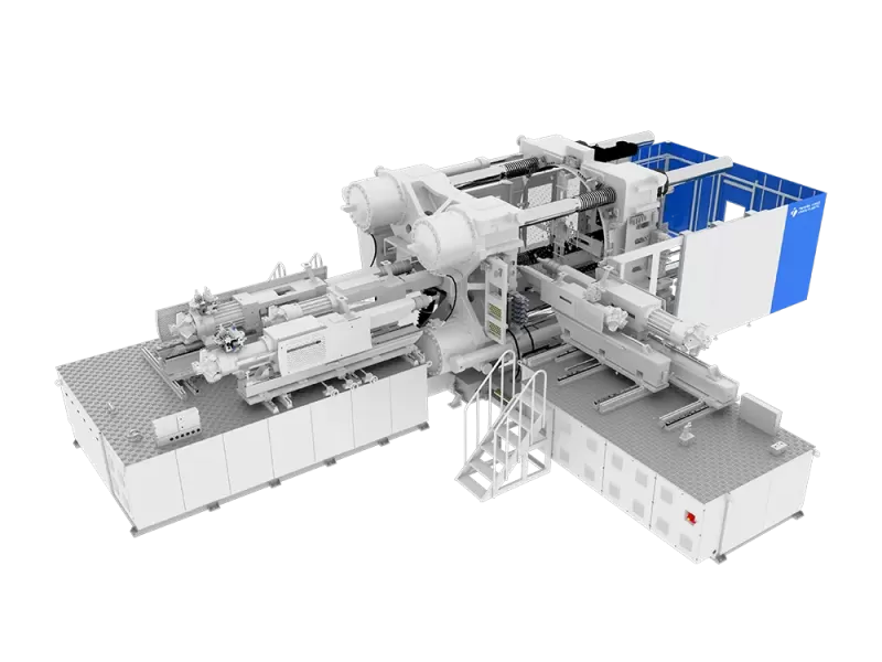
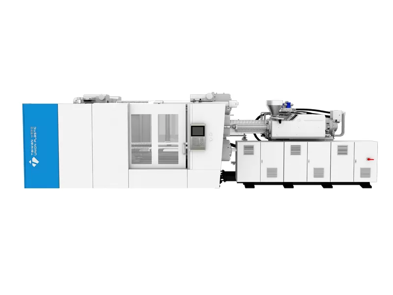
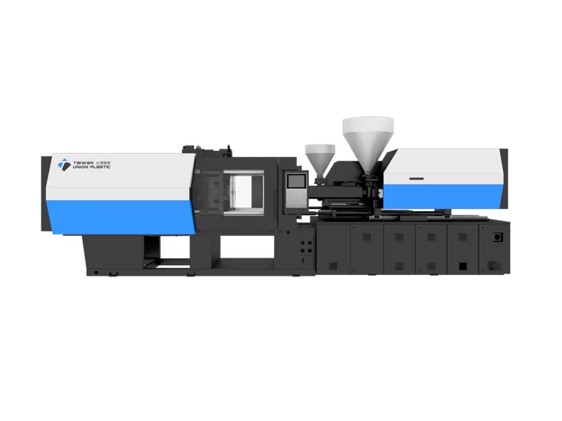
The two-plate structure with high modulus capacity is ideal for large, multi-color mold products. The modular injection molding platform supports two- to five-color multi-component processes.

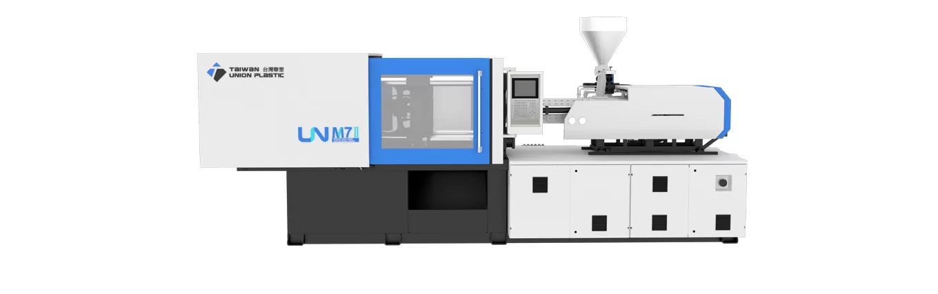 UN
Servo Hydraulic Injection Molding Machine
UN
Servo Hydraulic Injection Molding Machine
Thin-wall packaging turns injection molding into a race against cooling time. Cups, lids, food containers, dairy packaging and other lightweight products have long flow paths relative to their wall thickness, so the melt must reach the end of the cavity before the flow front freezes. At the same time, the finished part must remain dimensionally stable, visually consistent and strong enough for filling, sealing, stacking, transport and end use.
A high-speed packaging cell therefore depends on much more than a machine with a large injection-speed number. The mold must fill evenly, the injection unit must accelerate and decelerate predictably, the clamp must open and close quickly without sacrificing mold protection, plasticizing must finish inside the available cooling window, and the robot or IML system must complete its work without becoming the bottleneck.
TUP develops both UN-H thin-wall high-speed servo-hydraulic machines and high-performance electric or hybrid platforms for fast packaging applications. This guide explains how B2B buyers should evaluate such equipment, using published TUP performance data as practical examples while separating machine capability from cycle-time promises that depend on the complete mold and production cell.
A high-speed injection molding machine is an injection molding system engineered for rapid, repeatable melt delivery and short machine movements so that thin-wall or high-output products can be molded within a narrow cycle-time window.
High speed is often reduced to one specification: maximum injection velocity. That figure is important, but it does not describe the whole process. A packaging machine must accelerate the screw quickly enough to establish the required flow front, maintain controlled velocity through the cavity, transfer from velocity to pressure without excessive overshoot, recover the screw for the next shot, and coordinate mold movement with part removal.
The machine structure also has to remain stable during those rapid movements. Platen rigidity, tie-bar design, low-friction guidance, servo response and control sampling all affect repeatability. TUP’s UN-H platform, for example, is described as a thin-wall high-speed series using a reinforced platen design, a low-friction injection-unit arrangement and strengthened tie bars for high-speed operation. TUP publishes a clamping-force range of approximately 160–2500 metric tons and screw diameters of approximately 24–90 mm for the series.
That range shows why “high speed” is not synonymous with “small machine.” Packaging products can be compact and multi-cavity, but larger containers and industrial thin-wall items may still require substantial clamping force and shot volume. The correct high speed injection molding machine must therefore be sized around the actual mold and process, not around a generic packaging label.
Thin-wall packaging needs a high-speed injection molding machine because the melt loses heat rapidly in the cavity, leaving a short period in which the part can be filled before viscosity rises and the flow front freezes.
Wall thickness changes the entire molding problem. As the wall becomes thinner, flow resistance increases and the polymer contacts a large area of cold mold surface relative to its volume. The process therefore demands fast filling, an efficient runner and gate design, well-controlled melt temperature and strong mold cooling. If injection is too slow, the pressure required to continue filling can rise sharply or the part can short-shot before the cavity is complete.
Thin-wall packaging also operates under demanding economics. A fraction of a second may appear insignificant on one cycle, but it becomes meaningful over millions of parts. A 0.5-second reduction on a five-second cycle represents a 10% cycle-time reduction before downtime is considered. This is why packaging projects often justify higher-performance machinery when the annual volume is high enough.
Yet aggressive speed can create defects if it is not controlled. Excessive shear, burn marks, flash, gate blush, trapped air, part sticking and uneven filling can appear when the machine, mold and material are not balanced. The objective is not maximum speed at every stage. It is the shortest stable cycle that continues to produce acceptable parts within a robust process window.
For that reason, high-speed equipment should be evaluated together with the supplier’s injection molding solutions capability. A packaging cell can include mold engineering, IML, robot take-out, vision inspection, stacking, conveying and downstream handling. Improving only the injection phase may simply move the bottleneck to another operation.
The most important high-speed injection molding machine specifications are injection velocity and response, injection pressure, plasticizing capacity, mold movement, clamping stability and the control system’s ability to synchronize them.
Maximum injection speed is the headline specification because it affects how quickly the melt can travel through the cavity. TUP publishes a maximum injection speed of 450 mm/s for its ES all-electric platform and also cites that speed in its thin-wall packaging demonstrations. A buyer should still ask how the value is achieved: at what screw diameter, under what pressure load, and over what usable stroke?
Acceleration and response are equally important. A machine that theoretically reaches a high top speed but takes too long to accelerate may not deliver the expected benefit on a short injection stroke. Likewise, unstable deceleration near transfer can create pressure overshoot and flash. Control repeatability matters more than peak velocity alone.
Plasticizing capacity should be checked against cooling time. In a fast packaging cycle, screw recovery often needs to occur while the part cools. If plasticizing takes longer than cooling, the machine waits for the next shot and the apparent advantage of fast injection disappears. Screw diameter, screw design, motor power, back pressure and resin behavior all influence recovery time.
Clamp movement is another major contributor. TUP states that its ES platform can increase mold opening and closing speed by 20% compared with the reference traditional equipment used in its comparison. Fast mold movement can save time, but it has to be paired with effective mold protection and controlled approach near the mold faces. Damaging a high-cavity packaging mold to save a fraction of a second is not a valid productivity strategy.
Finally, the machine’s controller must coordinate the entire sequence. Packaging requires accurate timing among injection, hold, cooling, screw recovery, mold opening, robot entry, label placement or part take-out, mold closing and the next shot. A well-integrated control strategy is often what converts impressive component specifications into stable production.
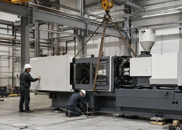
A high-speed injection molding machine reduces cycle time by shortening the filling phase and non-productive machine movements while overlapping compatible actions such as plasticizing, cooling and automation.
Cycle time should be broken into components before a buyer evaluates a new machine. The main stages are mold close, injection, pack/hold, cooling, screw recovery, mold open, ejection or robot take-out, and any label or insert placement. Some stages happen sequentially; others can overlap. The best improvement opportunity depends on which stage is currently limiting the cell.
If a five-second cycle includes only 0.4 seconds of injection but 2.5 seconds of cooling, doubling injection speed will not cut the total cycle in half. The project may gain more from improved cooling channels, lower part weight, faster robot movement or optimized mold-open stroke. Conversely, if a very thin cup takes nearly a second to fill and the process is pressure-limited, a higher-performance injection unit can have a major effect.
TUP has published a useful real-world sequence for a 130 g IML yogurt cup demonstration. The company reported a 4.7-second cycle at CHINAPLAS in April 2024, a 4.3-second cycle at the DMP Rubber and Plastics Exhibition in November 2024, and a 3.9-second live demonstration in April 2025. The reduction from 4.7 to 3.9 seconds is approximately 17%, matching the figure in TUP’s case headline.
The theoretical cycle throughput illustrates the economic importance. At 4.7 seconds, one cavity position can complete about 766 cycles per hour if there is no downtime. At 3.9 seconds, the theoretical rate rises to about 923 cycles per hour, an increase of approximately 20.5%. Actual saleable output will be lower because factories experience startup losses, quality checks, material changes, maintenance and other downtime, but the example shows how cycle-time reductions compound over high volumes.
Those demonstration values should not be used as a guaranteed cycle for another mold. A different cup weight, wall thickness, resin, cavity count, label, cooling-water temperature or robot will change the result. They are best used as evidence that the platform has been applied to short-cycle packaging, followed by a mold-specific trial.
A mold for a high-speed injection molding machine must support rapid filling, efficient venting, balanced flow, intensive cooling and fast, reliable ejection without flexing or creating excessive pressure loss.
The mold is often the dominant factor in packaging performance. A high-output press cannot compensate for an unbalanced runner, inadequate venting or weak cooling. Multi-cavity systems require each cavity to fill at nearly the same time; otherwise, the fastest cavities can overpack while slower cavities remain short.
Gate design should minimize unnecessary pressure loss while still producing an acceptable gate mark and separation behavior. Hot-runner systems are common in packaging because they can reduce runner waste and support multi-cavity layouts, but manifold balance and temperature control become critical. The mold should also provide adequate venting near the end of fill so trapped air does not create burns or excessive pressure.
Cooling is usually the longest part of an optimized injection-molding cycle. Cooling channels should be placed to remove heat uniformly from thick ribs, bases and corners while avoiding large temperature differences across the cavity. Conformal cooling may be considered for difficult geometries, but conventional channel design can also perform well when it is optimized around the part.
Mechanical durability matters because a packaging mold can experience millions of cycles. Slides, ejectors, hot-runner components and cavity surfaces must withstand fast repetitive motion. The machine’s mold-protection system should be tuned carefully, and the mold should include sensors or monitoring where a collision would be costly.
Automation and in-mold labeling affect a high-speed injection molding machine because robot entry, label placement, part removal and downstream handling must complete within the machine’s short open-mold window.
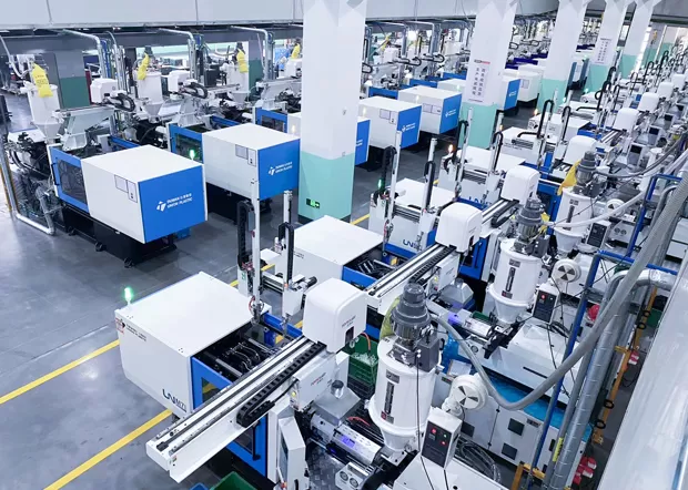
In-mold labeling can combine decoration and molding in one operation, reducing post-molding printing or labeling steps. The productivity advantage depends on robot speed, label separation, static charging or placement method, mold access and confirmation signals. If the robot needs too much time inside the mold area, the overall cycle can be dominated by automation rather than injection.
TUP describes IML as molding and labeling in a single step and publishes example machine data including mold opening and closing speed improvements of 20%, injection response below 40 ms and product-quality repeatability of 0.1% for the referenced system. Those figures demonstrate the type of coordination required in a high-speed IML cell, although the finished-part result remains application dependent.
Automation design should begin before the machine is ordered. Define the robot payload, reach, acceleration, label magazine, vision inspection, stacking orientation, conveyor interface and reject strategy. Confirm how the machine communicates with the robot and whether mold-open, ejector and core movements can be overlapped safely.
A useful target is to make the automation invisible to cycle time. If cooling takes 2.5 seconds and robot operations can be completed inside the unavoidable open/close window, automation adds little or no extra delay. If the robot needs a separate two-second handling step after cooling, the cell’s theoretical machine speed becomes irrelevant.
Energy use on a high-speed injection molding machine depends on the power demanded per cycle and the number of parts produced, so energy per hour and energy per kilogram should both be evaluated.
A faster machine can draw high peak power while still reducing energy per part if it produces significantly more parts in the same time. This is why simple comparisons of installed motor kilowatts can be misleading. The production team should measure specific energy consumption under a defined mold, resin and cycle.
EUROMAP 60.1 provides a standardized framework for classifying injection-molding machine energy efficiency using specific energy consumption and idle characteristics. It also cautions that only machines of similar size should be compared directly because screw diameter, clamping force and other factors influence consumption. For a real purchasing project, customer-specific testing or an agreed FAT cycle is more valuable than a generic energy class alone.
Electric and hybrid systems can be attractive in packaging because servo drives apply power according to motion demand and can support highly dynamic profiles. TUP states that its ES all-electric platform consumes 20%–40% less energy than traditional injection molding machines under the company’s stated comparison conditions. That range should be validated against the buyer’s actual part, cycle and local utility cost when calculating ROI.
Cooling systems, dryers, chillers, compressors, robots and hot runners also consume significant energy. A machine-only comparison can therefore miss the largest system-level opportunity. The correct KPI is often kilowatt-hours per thousand accepted parts or kilowatt-hours per kilogram of saleable product, measured across the full cell.
A high-speed injection molding machine comparison should match the drive and clamping architecture to the packaging mold, cycle-time target, cavity count, cleanliness needs and required automation.
| Machine Approach | Best Fit | Key Advantages | Main Checks | TUP Reference |
|---|---|---|---|---|
| Thin-wall servo hydraulic | High-output packaging requiring broad tonnage and mold flexibility | Fast injection, reinforced structure, strong clamping range | Hydraulic response, cooling, injection-unit sizing | UN-H, approx. 160–2500 t; 24–90 mm screw range |
| All-electric | Precision thin-wall products, clean cells, high repeatability | 450 mm/s published max injection speed, precise servo motion, energy advantages | Mold fit, shot size, automation and total investment | ES, approx. 90–450 t |
| Hybrid | Packaging needing electric injection dynamics plus hydraulic functions | Combines fast injection response with hydraulic clamping flexibility | System complexity and application-specific ROI | UN-E; HS-E |
| Special PET platform | Preforms and integrated bottle-production chains | Application-specific plasticizing and automation focus | PET drying, preform mold, downstream blow-molding interface | PET preform special machine |
| Barrel special machine | Large plastic packaging containers | Can integrate IML, heat transfer and handle installation | Large mold, shot size, post-processing automation | UN-B |
The table shows that “packaging machine” is not one category. A yogurt cup, bottle preform and large chemical pail all belong to packaging, but their ideal presses can be completely different. Buyers should therefore use the injection molding machine product range to compare architectures only after the product and mold requirements have been defined.
During FAT, ask the supplier to run an agreed resin, mold and automation sequence where practical. Record cycle time, injection time, peak pressure, cushion, recovery time, part weight, critical dimensions, reject rate and specific energy consumption. A short demonstration with incomplete data is less useful than a repeatable production test with an agreed acceptance standard.
These frequently asked questions summarize the main engineering and purchasing issues for a high-speed injection molding machine used in thin-wall packaging.
There is no universal threshold because screw diameter, injection rate, part geometry and pressure load matter. TUP publishes a maximum injection speed of 450 mm/s for its ES platform, but machine selection should be based on the mold’s actual filling requirement.
No. If cooling, plasticizing or robot handling is the bottleneck, faster filling may have only a small effect on total cycle time. The full cycle should be analyzed by stage.
No. High-speed platforms can also support multi-cavity lids, containers and other products where rapid filling and high output are required. The exact machine configuration depends on projected area, shot size and mold design.
Cooling is often the longest stage of an optimized cycle. Uneven or slow heat removal can extend cycle time and create warpage, shrinkage variation or sticking even when the machine fills rapidly.
Choose according to the mold and business target. Servo hydraulics provide flexibility and a broad tonnage range; all-electric machines emphasize precise servo motion and energy performance; hybrid machines combine electric injection with hydraulic functions.
Provide part drawings, resin grade, wall thickness, part and runner weight, cavity count, mold dimensions, target cycle, required IML or robot sequence, current process data and annual output. This allows TUP to size the clamp, injection unit and automation around the real application.
The best high-speed injection molding machine is the one that achieves a short, repeatable and energy-efficient cycle together with the mold, cooling, automation and downstream packaging process.
Thin-wall production is a system problem. High injection speed matters, but so do acceleration, pressure control, screw recovery, mold movement, venting, cooling, robot timing, quality control and long-run process stability. A stable 4-second cycle that runs for hours with low scrap can create more value than an unstable 3.5-second demonstration that cannot be sustained in production.
TUP’s published data offers useful reference points: UN-H spans approximately 160–2500 tons, the ES platform reaches a stated 450 mm/s maximum injection speed, and TUP documented a 130 g IML yogurt-cup cycle improving from 4.7 seconds in April 2024 to 3.9 seconds in April 2025. The next step for a buyer is to translate those platform capabilities into a mold-specific trial and total-cost model.